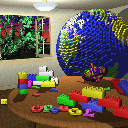
 0.0 |
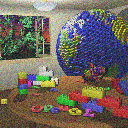 0.25 |
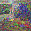 0.5 |
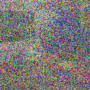 0.75 |

1.0 |
void Image::AddNoise(double factor);Adds noise to an image. The amount of noise is given by the factor in the range [0.0..1.0]. 0.0 adds no noise. 1.0 adds a lot of noise.
 0.0 |
 0.25 |
 0.5 |
 0.75 |

1.0 |
void Image::Brighten(double
factor);
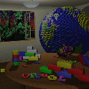
Changes the brightness of an image by interpolating between the original image and a black image (factor = -1.0) or a white image (factor = 1.0). Interpolation with the black image darkens the image, and interpolation with the white image brightens it. See Graphica Obscura.
 0.0 |
 0.5 |
 1.0 |
 1.5 |
 2.0 |
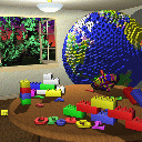
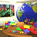
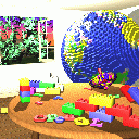
void Image::ChangeContrast(double factor);Changes the contrast of an image by interpolating between a constant gray image (factor = 0) with the average luminance and the original image (factor = 1). Interpolation reduces contrast, extrapolation boosts contrast, and negative factors generate inverted images. See Graphica Obscura.
 -0.5 |
 0.0 |
 0.5 |
 1.0 |
 1.7 |
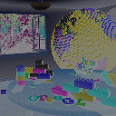
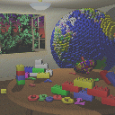
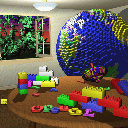
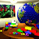
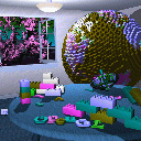
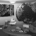
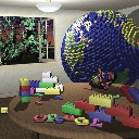
void Image::ChangeSaturation(double factor);Changes the saturation of an image by interpolating between a gray level version of the image (factor = 0) and the original image (factor = 1). Interpolation decreases saturation, extrapolation increases it, and negative factors preserve luminance but invert the hue of the input image. See Graphica Obscura.
 -1.0 |
 0.0 |
 0.5 |
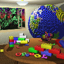 1.0 |
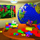 2.5 |
Image* Image::Crop(int x, int y, int w, int h);Extract a sub image from the image, at position (x,y), width w, and height h.
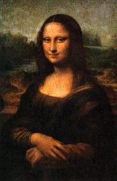 |

Crop(42,16,85,93) |
void Image::ExtractChannel(int channel);Extract a channel of an image. Leaves the specified channel intact. Sets all other ones to zero.
 Original |
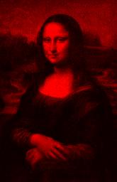 Red |
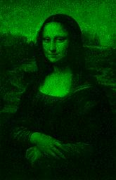 Green |
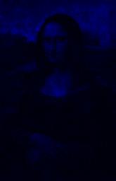
Blue |
void Image::Quantize(int nbits);Converts an image to nbits bits per channel using uniform quantization.
The number of levels per channel is L = 2nbits. The size of each input interval is a = 256 / L. The size of each output output interval is b = 255.0 / (L - 1). Each component c is mapped to floor(c / a) * b. The graph below shows the resulting staircase function for the case nbits = 3
All the pixels within the same input interval are mapped to the same output level. Notice the contours that appear when nbits is low.
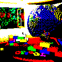 1 |
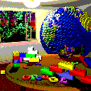 2 |
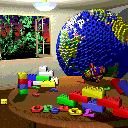 3 |
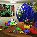 4 |
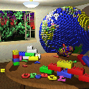 5 |
void Image::RandomDither(int nbits);Converts an image to nbits bits per channel using random dithering. It is similar to uniform quantization, but random noise is added to each component during quantization. Using a and b as defined for quantization, each component c is mapped to floor(c / a + noise()) * b. The function noise() returns a random floating point number in the interval [-0.5,0.5].
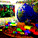 1 |
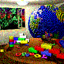 2 |
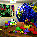 3 |
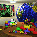 4 |
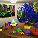
5 |
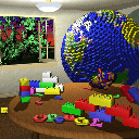
void Image::OrderedDither(int nbits);Converts an image to nbits bits per channel using ordered dithering. It is similar to uniform quantization, but pseudo-random noise is added to each component before quantization. The amount of noise added is determined by a Bayer's pattern matrix. The following examples used the matrix
| Bayer4 | = | 15 | 7 | 13 | 5 |
| 3 | 11 | 1 | 9 | ||
| 12 | 4 | 14 | 6 | ||
| 0 | 8 | 2 | 10 |
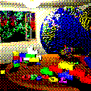 1 |
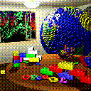 2 |
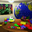 3 |
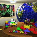 4 |
5 |
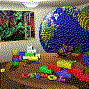
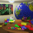
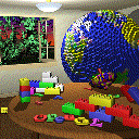
void Image::FloydSteinbergDither(int nbits);Converts an image to nbits per channel using Floyd-Steinberg dither with error diffusion. Each pixel (x,y) is quantized, and the quantization error is computed. Then the error is diffused to the neighboring pixels (x + 1, y), (x - 1, y + 1), (x, y + 1), and (x + 1, y + 1) , with weights 7/16, 3/16, 5/16, and 1/16, respectively.
 1 |
 2 |
 3 |
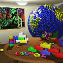 4 |
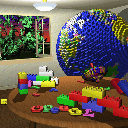
5 |
void Image::Blur(int n);Blurs an image by convolving it with a n x n Gaussian filter. In the examples below, the Gaussian function used was

and the value for sigma was chosen so that the weight at the center of the filter is 1.0, and the weight at a corner of the filter is 1 / (6 * r2 + 4 * r + 1), where r is n div 2.
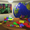 3 |
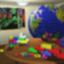 7 |
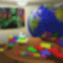 11 |
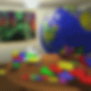 15 |
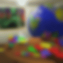
19 |
void Image::EdgeDetect();Detect edges in an image by convolving it with an edge detection kernel. In the example below, the kernel used was
|
-1 |
-1 |
-1 |
|
-1 |
8 |
-1 |
|
-1 |
-1 |
-1 |
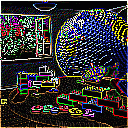
Image *Image::Scale(double sx, double sy);Scales an image in x by sx, and y by sy. The result depends on the current sampling method (point, bilinear, or Gaussian). In the example below, the size of the Gaussian filter is 3x3.
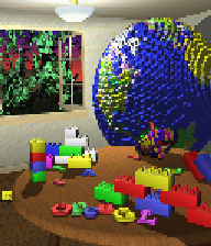 Point |
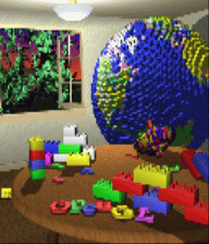 Bilinear |
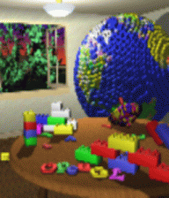
Gaussian |
Image *Image::Rotate(double angle);Rotates an image by the given angle. The result depends on the current sampling method (point, bilinear, or Gaussian). In the example below, the size of the Gaussian filter is 3x3.
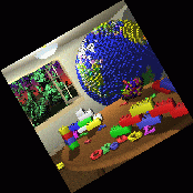 Point |
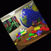 Bilinear |
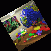 Gaussian |
void Image::Composite(Image *bottom, Image *top, Image *result);Composites the bottom and top images into the result image.
Original Images
Brazilian soccer team ("seleção") Me
Auxiliary Images
image -constantColor 373 512 0 0 0 > black.bmp
image -constantColor 373 512 0 0 255 > blue.bmp
Final Image
image -composite black.bmp front.bmp front_mask.bmp < selecao.bmp > final.bmp
void Image::Fun();Warps an image using a creative filter of your choice. In the following example, each pixel is mapped to its corresponding scaled polar coordinates. The artifacts of point sampling are very noticeable in this example.
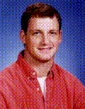 Original |
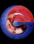 Point |
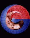 Bilinear |
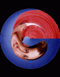
Gaussian |
Image* ImageMorph (Image* I0, Image* I1, int numLines, Line* L0, Line* L1, double t);Morph two images using [Beier92]. I0 and I1 are before and after images. L0 and L1 are corresponding line segments. t is the morph time, between 0 and 1.
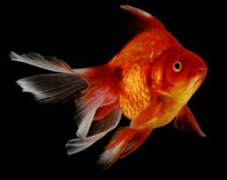
before |
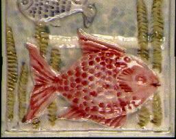
after |