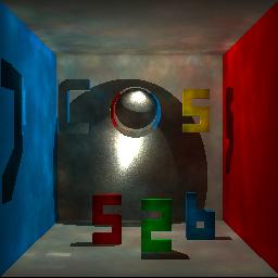
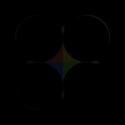
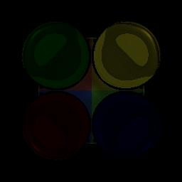
Photon Mapping
COS526 - Advanced Computer Graphics, Fall 2014
Brian Matejek
Photon Tracing
Photon emission:
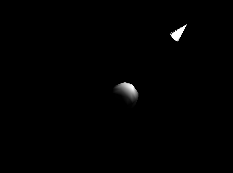
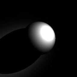
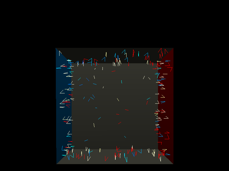
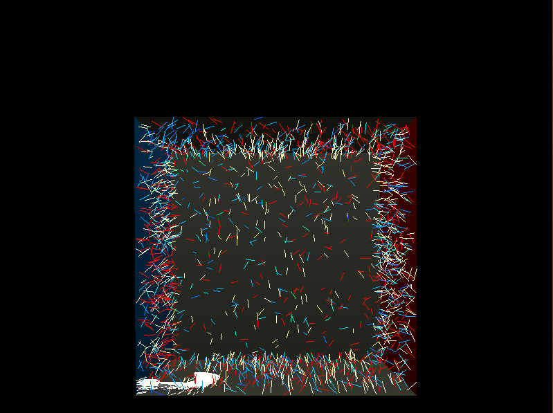
For each type of light source I show three pictures:
(1) the photons as they are emitted from the light source
(2) the photons as they intersect with the scene, showing both the incident direction and normal
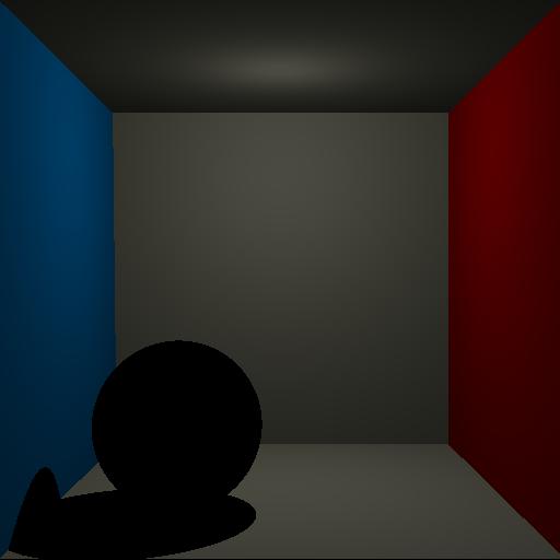
(3) the direct illumination calculation during rendering (ignoring any indirect illumination)
Area Light Source
For area light sources, a random position was generated on the circle representing the light's location. This was achieved by randomly generating two values, an angle and a radius value. These two values created a random point on the circle on the plane z=0. I then transformed this point onto the desired circle on the plane defined by light->Direction(). The direction was sampled according to a cosine distribution.
Directional Light Source
For directional light sources, I created a large circle outside of the scene defined by a normal equal to the direction of the light. The circle was made larger than the projection of the scene bounding box onto the plane. I generated the desired number of photons such that each photon intersected with the scene.
Point Light Source
For point light sources, I randomly generated a ray from the position of the point light source in a direction randomly choosen equally.
Spot Light Source
For spot light sources, all of the rays started at the same location-the position of the spot light. I sampled directions according to the distribution of cos(angle)^sd. If the angle generated exceeded the cutoff, I sampled again until I received a valid direction.
Photon scattering, Russian Routlette, and BRDF importance sampling:
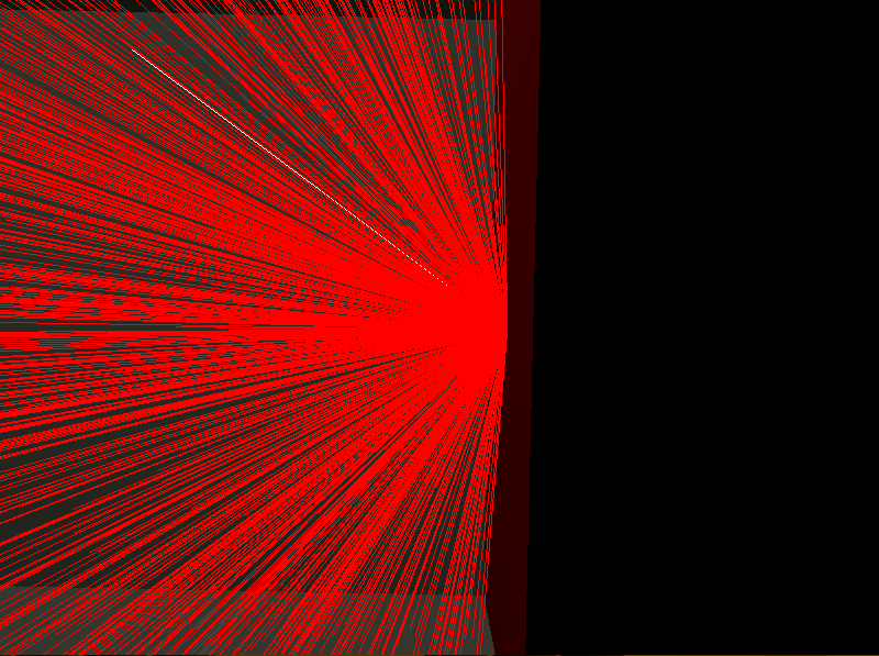
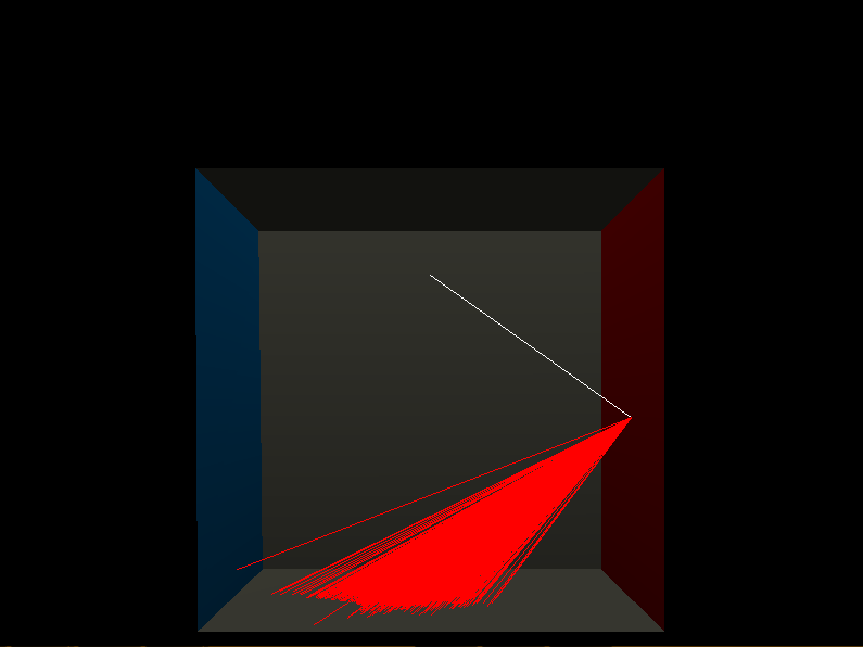
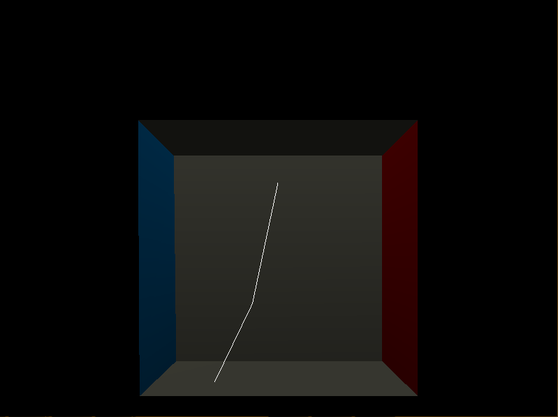
Photon scattering followed the Jensen paper, and the powers of each photon were recomputed using the formula provided on Jensen01 page 20-21. At each surface intersection, a ray was generated, either follow a direction of diffuse, specular, or transmitted reflection. After 5 iterations, the photon path was terminated, since some of the scenes contained non-physical surfaces that had kd values that amplified the power. The directions of the outgoing diffuse and specular reflection followed the notes from Jason Lawrence. Transmitted rays always followed the path of perfect refraction according to Snell's law. In the image below, I changed the wall material to be specular with n=100.
| Diffuse |
Specular |
Transmission |
 |
 |
 |
Photon storage:
I used the provided R3Kdtree class to store the photons. There were two R3Kdtrees, one for caustic photons and one for global photons. Since direct illumination was calculated separately during rendering, the first photon-surface interaction was not included in the global photon map.
Multiple photon maps:
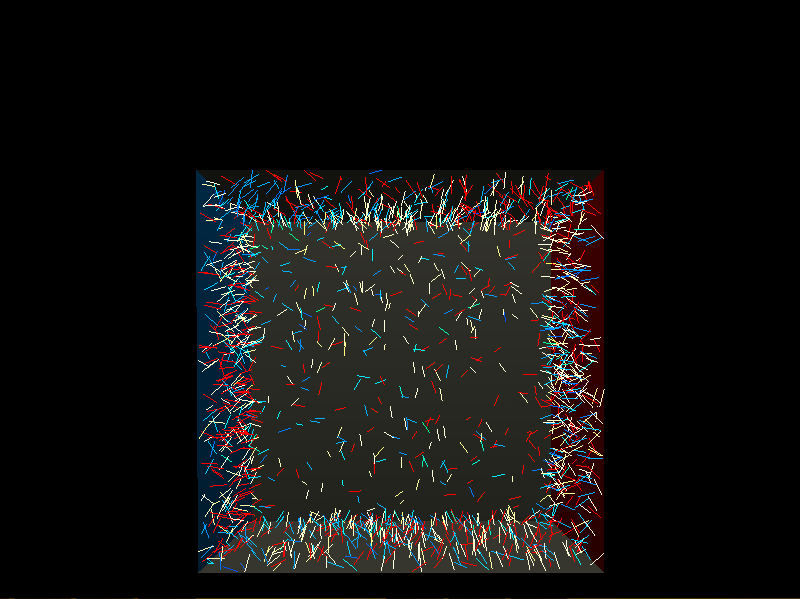
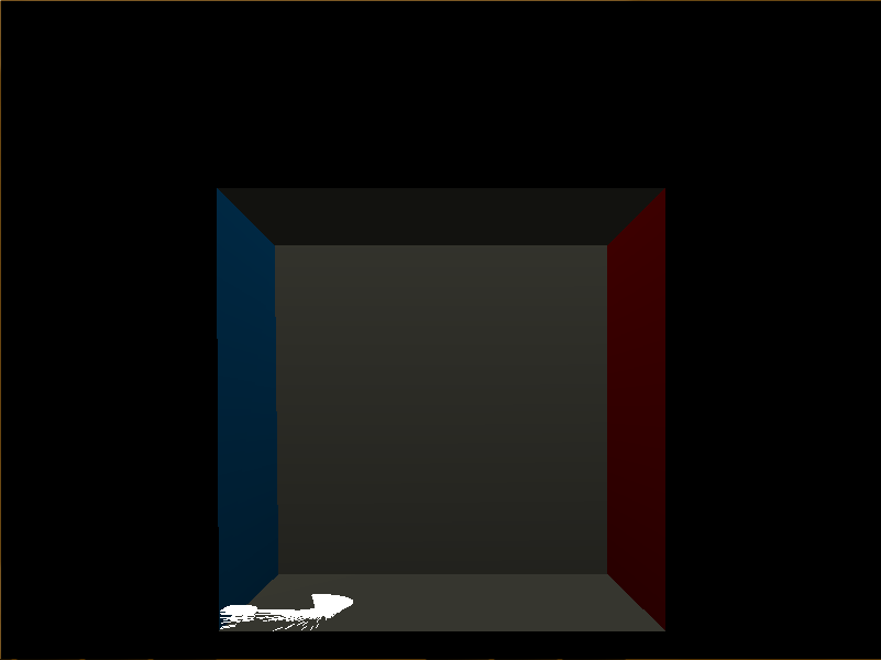
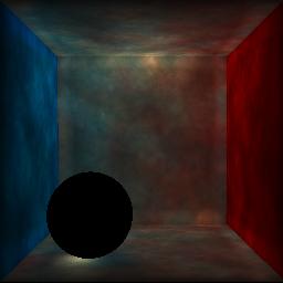
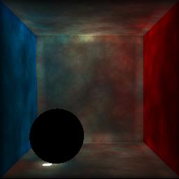
I used a global photon map for all photons L(S|D)*D and a caustic photon map for all photons LS+D. Any photon that was caustic is excluded from the global photon map. I created two photon maps, one that started with many more photons. I took the generated caustic photons from this map and added them to the generated global photons from the small photon map. The second row of photos shows the result of only using indirect illumination from the photon maps.
| Global Photons |
Caustic Photons |
Both |
 |
 |
 |
 |
 |
 |
Photon map visualization:
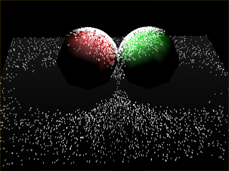
Almost all of the above images utilized the photon visualizer that I created. The visualizer shows photon incident directions, surface normals, and the color of the incoming light (normalized for power). I also created a photon visualizer that showed the paths that the photons took in its entirely, allowing a user to see the changes in power after number diffuse surface interactions. Both of these visualizations show the interactions of 100 emitted photons.
Rendering
Camera ray tracing:
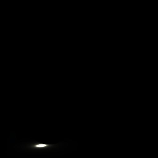
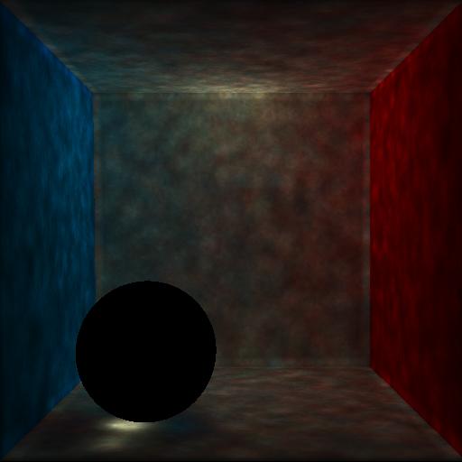
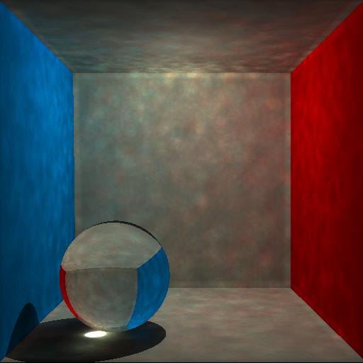
I implemented the camera ray tracing method discussed in Jensen01, where the radiance integral is computed by summing direct illumination, specular and glossy reflection, caustics, and multiple diffuse reflections. The following images were generated with 100,000 emitted photons.
| Direct |
Caustics |
 |
 |
| Diffuse |
Combined |
 |
 |
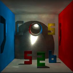
Below is an image generated with 1,000,000 photons and a radiance estimate size of 250 photons.

Other Renderings:

Radiance estimation:
N samples were used to estimate the radiance at a given point for both caustic and global photon maps. The images below show the result of varying values of N (number of pixels in estimate).
Pixel integration:
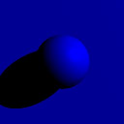
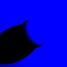
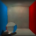
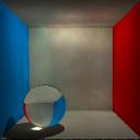
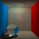
When generating N rays, for pixel i, j, I did a bilinear interpolation between the rays through pixels (i - 1, j), (i + 1, j), (i, j - 1), and (i, j + 1), by generating two random numbers, alpha and beta. I thought the most varies results would occur with small images, since the vectors would have the greatest difference then. I used N = 1, N = 7, and N = 25 for varying small sizes. In these cases, some aliasing occurs for N = 1 around the sphere but is generally corrected in the cases of 7 and 25.
|
1 |
7 |
25 |
| 128x128 |
 |
 |
 |
| 96x96 |
 |
 |
 |
| 64x64 |
 |
 |
 |
Art
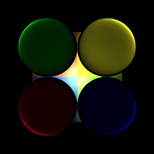
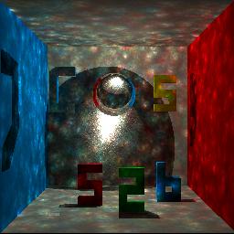
For the art portion, I played around with different lighting techniques. The four spheres in front transmit all light and the boxes behind are completely diffuse. I wanted to see how much I could change the image by varying the lighting positions.
